FastenersFromTurkey — Bursa, Turkey · sales@fastenersfromturkey.com Part of the MetalFromTurkey group · Bursa-based industrial fastener supplier and exporter serving international buyers
Fasteners From Turkey · Round and Square Bend Supply

Round and Square U-Bolts for Pipes, Frames and Equipment

FastenersFromTurkey supplies round and square U-bolts from Turkey for pipes, frames and equipment. Bend form, interface dimensions, thread, material, mechanical requirements, finish, inspection, quantity and export scope are confirmed against the drawing or specification for each RFQ.

  • Drawing-led review
  • Confidential specification handling
  • Export-document coordination
Round and square U-bolts supplied from Turkey for pipes, frames and industrial equipment

Round and square U-bolts supplied from Turkey for pipes, frames and industrial equipment

RFQ Qualification

Round and square U-bolt qualification summary

Confirm these order-specific inputs before quotation.

Fasteners From Turkey Confirmed per RFQ
Round and square U-bolt RFQ qualification fields
Field Order input Confirmation
Product scope Round or square U-bolt for the stated pipe, frame or equipment interface Type and application confirmed per RFQ
Standard/drawing Controlled drawing or ASME B18.31.5 within its stated scope Governing revision confirmed per RFQ
Dimensions/thread Bend form, rod diameter, inside width, leg length, bend radius, thread and tolerances Dimensional inputs confirmed per RFQ
Material/mechanical Material, grade or property class and required mechanical values Order requirement confirmed before quotation
Finish/coating Finish, coating and corrosion requirement for the stated service Finish scope confirmed per RFQ
Documentation Required certificate, inspection, test or TPI scope Availability and deliverables confirmed per order
Commercial Quantity, MOQ drivers, tooling if required, packing, Incoterm and destination Commercial basis confirmed in the quotation
Supplier role FastenersFromTurkey supplies round and square U-bolts from Turkey. Order-specific supply scope confirmed from the RFQ

Values remain order-specific until confirmed in the quotation.

Drawing-led Bend form, dimensions and tolerances confirmed against the controlled drawing
ASME B18.31.5 Inch-series bent-bolt reference applied within its stated scope
Labeled dimensions Rod diameter, inside width, leg length, thread and bend radius defined per RFQ
EXW–CIF Export terms reviewed with destination and quantity
Bend form and specification scope

What is reviewed before a round or square U-bolt is quoted

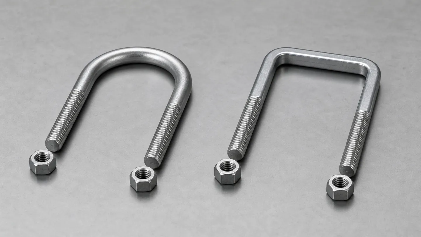
Round and square bend forms solve different interface problems. Selection starts with the shape that the crown must follow and the plate, bracket or member that the legs must pass around. Neither form is universally stronger, safer or more resistant to rotation; those outcomes depend on the complete joint geometry, material, clamp arrangement and engineering validation.

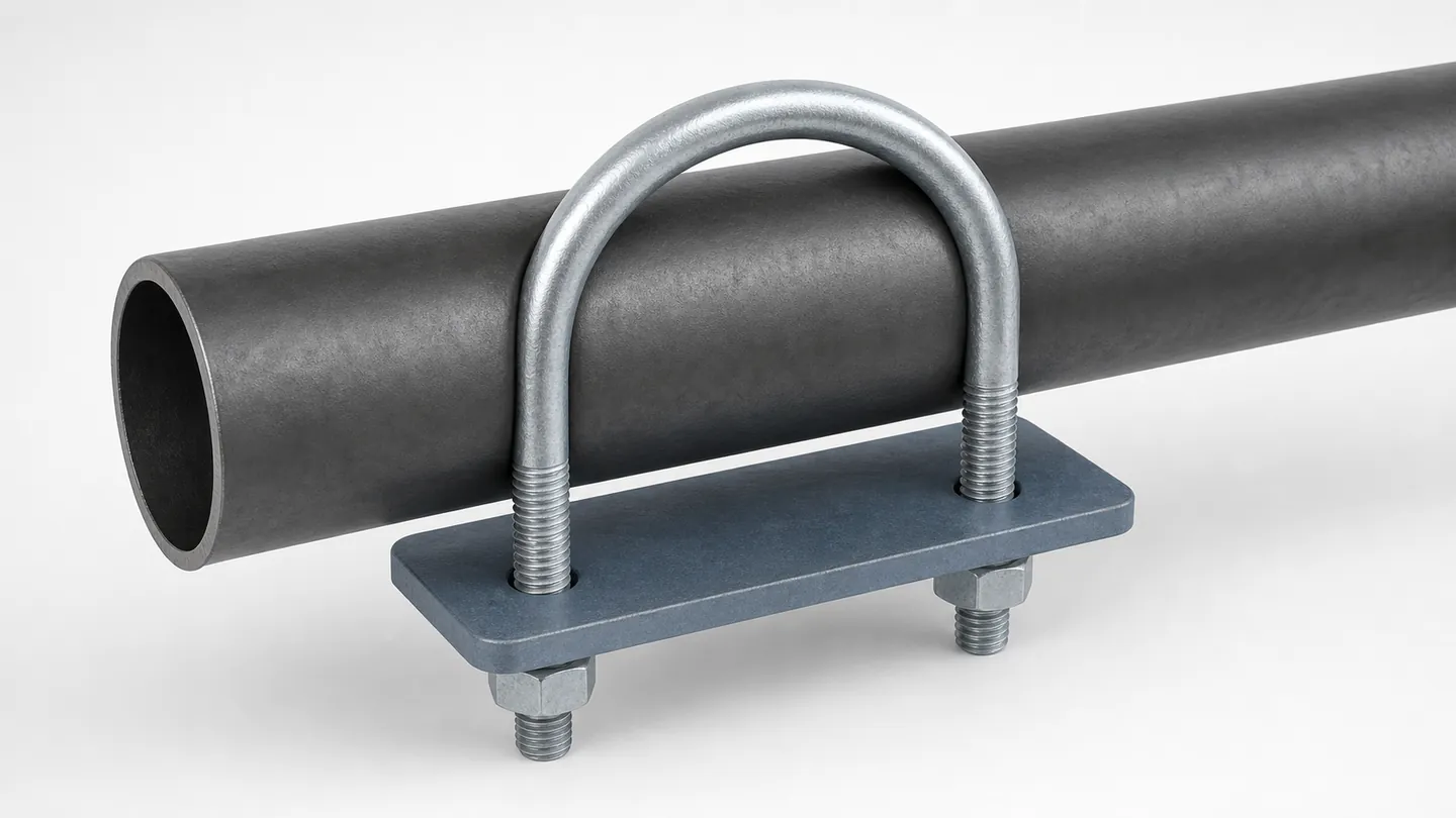
Round U-bolt positioned around a pipe with a mounting plate and threaded nuts

Round U-bolts for pipe, tube and curved interfaces

A round-bend U-bolt should follow the curved interface without being treated as a universal pipe clamp. State the pipe or tube outside diameter, insulation or liner if present, required clearance, support plate details and whether the dimension applies before or after coating. The inside width and bend radius must be defined consistently; a nominal pipe description alone may not establish either value.

Review bend-form selection
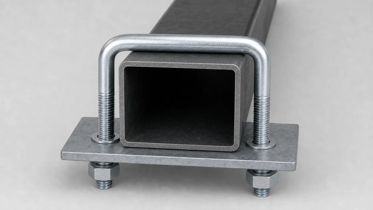
Square U-bolt fitted around a rectangular frame section with a mounting plate and nuts

Square U-bolts for frames and rectangular sections

Square U-bolts are commonly specified around rectangular tubing, frames, brackets and equipment members. The drawing should identify the section width and height, outside corner radius, clearance, plate-hole spacing and any restriction on the crown radius. A square bend still uses formed round rod, so the corners require a defined bend radius rather than an impossible sharp internal corner.

See the square-section inputs
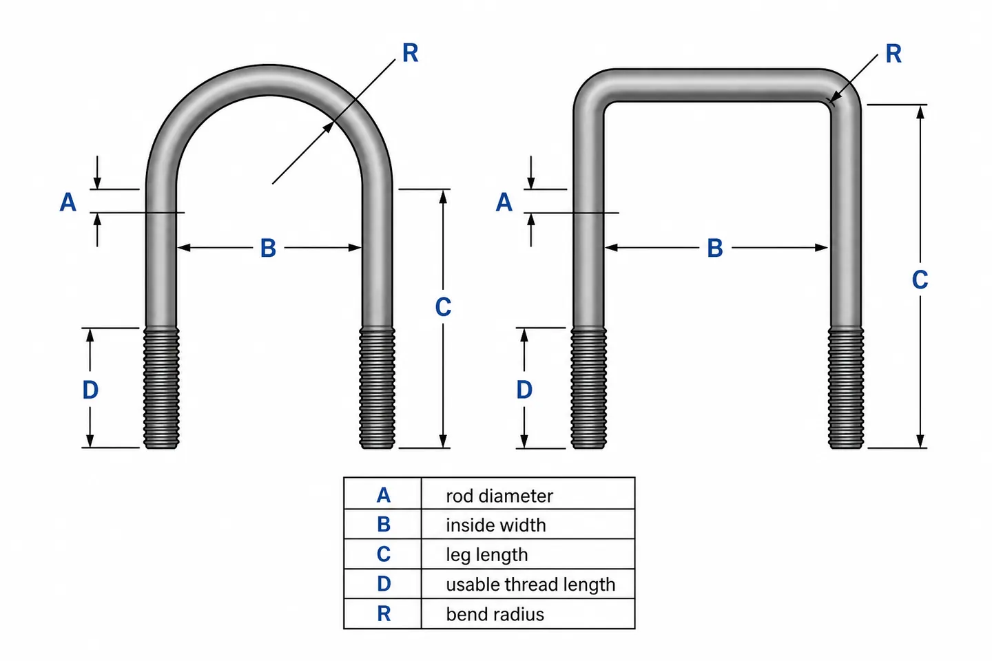
Round and square U-bolt diagram showing rod diameter, inside width, leg length, thread length and bend radius

How to specify round and square U-bolt dimensions

Searches for round U-bolt sizes or square U-bolt sizes often start with one nominal value. A quotable specification needs a consistent dimension convention and enough information to reproduce the interface. Include the bend form, rod diameter, inside width, leg length or inside height, usable thread length, thread designation and pitch, bend radius, leg equality, tolerances and units.

Review dimension requirements
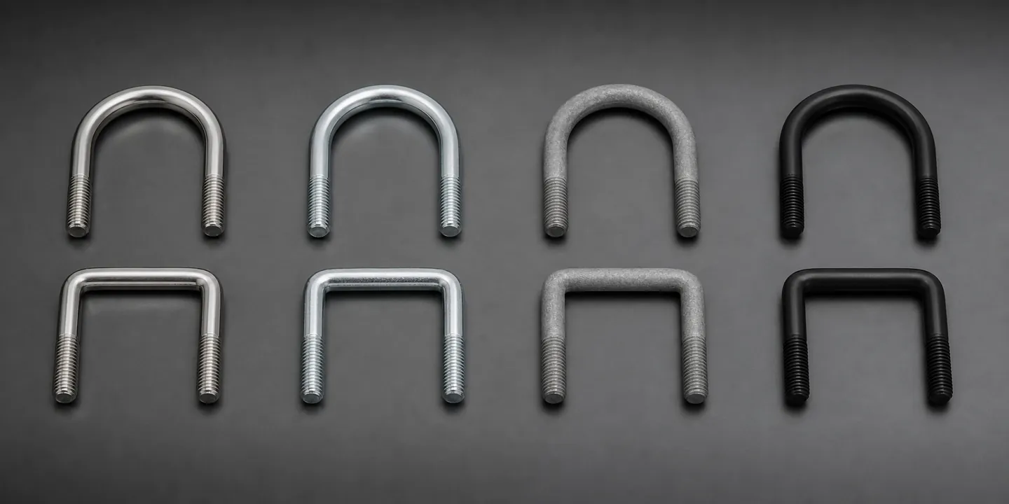
Round and square U-bolt finish samples prepared for coating and documentation review

Materials, mechanical requirements and finishes

Define carbon steel, alloy steel or stainless steel through an exact material or ordered specification rather than a generic family name. Finish selection begins with the service environment and joint controls: specify the coating system or standard, thickness, appearance limits, corrosion-test method and white- or red-corrosion criterion. No universal grade, coating, salt-spray duration or load rating is implied by the photographs.

Request Quote
Select by mating surface

Round vs square U-bolts and the dimensions that follow

Selection starts with the mating interface, then moves to a measurement convention that both parties can reproduce. The table entries below identify the typical interface, the critical details and the error that most often makes a request unquotable.

Round bend — pipe, tube, conduit or another curved member

Critical details: pipe outside diameter, inside width, bend radius and clearance. Common error: selecting from nominal pipe size without confirming actual outside diameter.

Square bend — square or rectangular hollow section, frame or bracket

Critical details: section width and height, corner radius, inside width and leg length. Common error: providing only a width while omitting rod, height, thread and radius.

How to measure a square U-bolt

Measure the rod diameter across an unthreaded straight section. Measure inside width between the legs, not across the outside surfaces, unless the drawing explicitly uses an outside convention. Define leg length from a stated crown or tangent datum to the end. Record usable thread length, pitch and thread class, then identify the bend radius and whether the legs must be equal. A sample should be labeled as an approved master, a worn service part or a reference only.

Metric and inch thread requirements

For a metric round U-bolt, specify the ISO metric thread designation, pitch and tolerance class. For inch requirements, state UNC or UNF, nominal diameter, threads per inch and thread class. Confirm the mating nuts and washers, coating allowance and any thread-gauge requirement. Metric property classes and SAE grades are not automatic substitutes because their thread systems, scopes and acceptance rules differ.

Shape-specific custom dimensions and drawing control

Custom square U-bolts may include unequal legs, non-standard radii, special end details, offsets or restricted thread runout. Mark every deviation on a controlled drawing with revision status and tolerances. Broader heavy-duty, load-specific or extensively engineered requirements need a full application review rather than a size-only quotation.

Discuss round or square bend requirements

RFQ dimension fields

How to define the required dimensions

A quotable specification needs a consistent dimension convention and enough information to reproduce the interface. Include the bend form, leg equality, tolerances and unit system alongside the values below. A dimensioned drawing is preferred.

SymbolRFQ dimensionDefinition to provide
ARod diameterFinished or pre-coating basis, tolerance and units
BInside widthClear distance between legs at the drawing-defined location
CLeg length or inside heightState the measurement datum and whether an overall length is also required
DUsable thread lengthThreaded engagement available on each leg, excluding incomplete runout
RBend radiusInside, centerline or drawing-defined radius with tolerance
Standards scope

Standards and drawing requirements

Standards must be applied within their stated scope. A dimensional standard does not automatically define material strength, coating, fatigue performance or suitability for the buyer's joint.

ReferenceAppropriate useBoundary
ASME B18.31.5General and dimensional requirements for inch-series bent bolts, including round- and square-bend U-boltsDoes not replace the ordered material, mechanical, finish or application requirements
DIN 3570Round-steel straps for tubes from NW 20 to 500Round pipe-fastening lane only; not a universal square U-bolt standard
SAE J429Mechanical and material requirements for qualifying inch-series steel U-bolts within scopeNot a dimensional or complete joint-design standard
ISO 898-1Mechanical and physical properties for qualifying metric carbon- and alloy-steel fastenersDoes not define corrosion, fatigue or torque-to-clamp performance
Customer or OEM drawingGeometry, tolerances, interface, special tests and application acceptanceUse the current controlled revision and approved deviations
Standards lanes

Which reference governs which requirement

Each reference below controls only what its own scope covers. Buyer evidence — drawing, grade, dimensions and acceptance criteria — must accompany any standard cited in the RFQ.

ASME B18.31.5 for inch-series bent bolts

When ASME B18.31.5 is called out, identify the applicable bend form and dimensional table together with the ordered size and tolerances. Do not assume that every table, material or finish is available from every manufacturing route. The purchase requirement should state any mechanical-property and coating specification separately.

DIN 3570 for round pipe-fastening straps

DIN 3570 is relevant when the requirement is a round-steel strap for a tube within its defined range. It should not be transferred to square-bend frame fasteners or unrelated U-bolt applications. DIN 525 is not used here: its current scope covers studs for welding, not U-bolts.

Mechanical properties and customer specifications

The RFQ should name the governing mechanical-property specification, grade or property class, material and required test basis. For safety-critical, fatigue-sensitive or load-specific joints, the customer or OEM specification must also define the application validation and installation controls. Any proposed substitution requires customer engineering approval.

Review quality and documentation support

Materials and finishes

Materials, mechanical requirements and finishes

Define carbon steel, alloy steel or stainless steel through an exact material or ordered specification rather than a generic family name. Where applicable, state heat treatment, hardness, tensile or proof requirements, test method and sampling plan.

Material, mechanical and thread requirements

Thread requirements should identify metric or UNC/UNF form, pitch, class and whether a rolled or cut thread is required by the drawing. Heat treatment, hardness, tensile or proof requirements, test method and sampling plan are stated where applicable.

Finish, corrosion and friction controls

Finish selection begins with the service environment and joint controls. Specify the coating system or standard, thickness, appearance limits, corrosion-test method and white- or red-corrosion criterion. If friction affects installation, include the approved friction or lubrication condition and mating-hardware compatibility.

Hydrogen-embrittlement controls for high-strength parts

High-strength electroplated parts may require documented hydrogen-embrittlement prevention and relief controls; an alternative coating route still needs part-specific approval. No universal grade, coating, salt-spray duration or load rating is implied by the photographs. Availability and evidence are confirmed for the selected manufacturer and order.

Width identifies only one part of a U-bolt. Before approval, confirm the bend form, rod diameter, height or leg length, usable thread, bend radius, tolerances and the actual mating interface; otherwise two parts described by the same width may not be interchangeable.

Applications

Applications and selection boundaries

Each application defines its own interface and technical controls. Select the bend form from the mating member, then confirm the additional information the manufacturing route needs.

Pipe, tube or conduit restraint — select round bend

Additional information: outside diameter, clearance, support plate and environment.

Rectangular frame or equipment member — select square bend

Additional information: section width/height, corner radius, plate and hole spacing.

Leaf spring, axle, trailer or suspension joint — application-specific route

Additional information: OEM drawing, spring/axle interface, validation and installation procedure.

Heavy-duty or load-specific assembly — drawing-led engineering review

Additional information: load case, fatigue criteria, material, coating and approved test plan.

Where other requirements belong

Selection boundaries and adjacent routes

A bend-shape page cannot carry application-specific validation or full custom engineering. Use the route that matches the governing requirement.

Trailer and suspension U-bolts

For a vehicle suspension joint, use the dedicated trailer and suspension U-bolts route. Axle and spring geometry, clamp-load controls, fatigue validation and the OEM installation procedure make that requirement application-specific rather than a simple round-versus-square selection.

Custom and heavy-duty U-bolts

Heavy-duty, load-specific or extensively drawing-controlled U-bolts require a separate engineering review. Submit the load case, duty cycle, mating parts, material, coating, test plan and approval requirements so the appropriate custom route can be confirmed. The broader U-Bolts family helps buyers compare requirement paths without moving that engineering depth onto a bend-shape page.

Why width alone is not a complete U-bolt specification

A request for a square U-bolt 3 inches wide or a 6 inch wide square U-bolt identifies only the inside-width concept — and even that needs a defined measurement convention. The quote still requires rod diameter, leg length or height, thread, bend radius, tolerances, material, finish and quantity. A labeled drawing prevents a catalogue convention from being mistaken for the buyer's functional requirement.

Inspection and documents

Inspection and documentation requirements

Inspection should be tied to measurable order criteria. Depending on the approved RFQ and selected manufacturer, the evidence package may include a controlled drawing, dimensional report, thread-gauge results, material or mechanical certificate, coating-thickness report, corrosion-test report, first-article or PPAP documents, third-party inspection, batch traceability and export documents.

Dimensions, tolerances and thread

For dimensions and tolerances, define the drawing revision, critical dimensions and sampling against the agreed inspection plan. For thread, define the designation, pitch, class and gauge method; a thread inspection record is issued when ordered.

Material, mechanics and finish

For material and mechanics, define the grade or specification, heat or batch and test requirements against the supplier-confirmed certificate and test scope. For finish, define the system, thickness, corrosion and friction criteria against the approved coating route and ordered reports.

Export documentation and supplier boundary

For export documentation, define origin, packing, labels and destination fields for the commercial order and shipping route. FastenersFromTurkey coordinates the request but does not transfer one factory's certificates or capabilities to another manufacturing route.

Review quality and documentation support

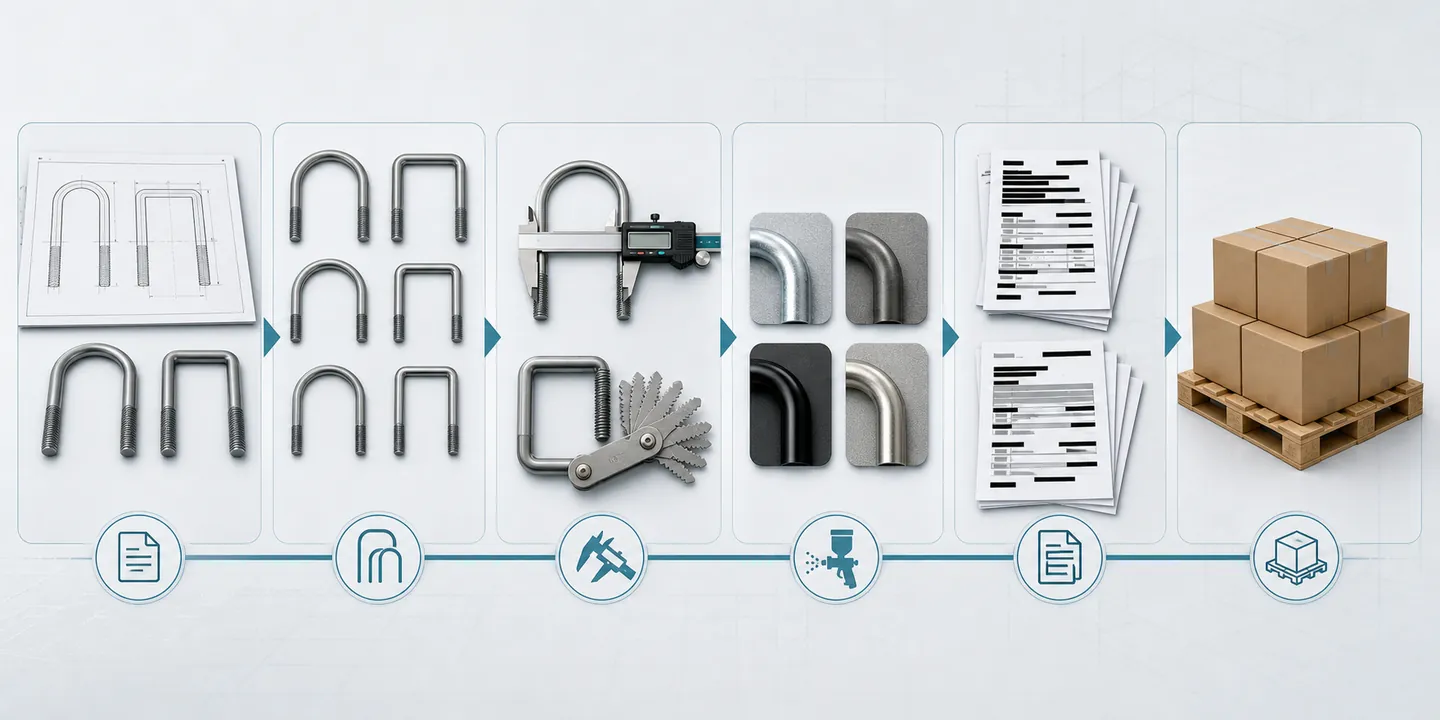
From specification to export

How we supply round and square U-bolts from Turkey

  1. 01

    Specification and drawing review

    FastenersFromTurkey is a Bursa-based B2B supplier and exporter. We review the controlled drawing or applicable standard and revision, the round or square bend form and the mating-interface details.

  2. 02

    Dimensions, thread and material check

    We confirm rod diameter, inside width, leg length or height, thread length and bend radius; the metric or UNC/UNF thread designation, pitch and class; and the material, grade or mechanical-property requirement.

  3. 03

    Confirm order-specific feasibility

    We review a complete round or square U-bolt requirement, confirm manufacturing capability and supply scope, and align specification clarifications, documentation, packaging and shipment terms. Production responsibility is confirmed for the specific order.

  4. 04

    MOQ, timing, inspection and export terms

    Quantity and annual demand, packaging, destination, requested delivery and the preferred EXW, FOB, CFR or CIF basis are reviewed. MOQ, tooling, lead time, document availability and shipment terms are confirmed for the selected manufacturing route and actual order.

Discuss Round or Square Bend Requirements

Round and square U-bolt FAQ

Frequently asked questions

What is the difference between round and square U-bolts?

A round-bend U-bolt follows a curved interface such as pipe or tube, while a square-bend U-bolt is shaped for a square or rectangular section, frame or bracket. The mating surface, bend radius, dimensions and joint design determine the correct form.

What dimensions are required to quote a round or square U-bolt?

Provide the bend form, rod diameter, inside width, inside height or leg length, overall length if used, thread length and pitch, bend radius, leg equality, tolerances and unit system. A dimensioned drawing is preferred.

Does ASME B18.31.5 define material strength?

ASME B18.31.5 establishes general and dimensional requirements for inch-series bent bolts, including round- and square-bend U-bolts. The ordered material, mechanical properties, finish and application requirements must also be specified.

When does DIN 3570 apply to a U-bolt?

DIN 3570 applies to round-steel straps for tubes from NW 20 to 500. It is relevant to the round pipe-fastening lane and should not be used as a universal standard for square-bend or unrelated U-bolt applications.

Can square U-bolts be used for leaf springs?

A suspension or leaf-spring application must follow the axle, spring pack, plate, customer drawing and OEM engineering requirements. Use the trailer and suspension U-bolt specification route for application-specific selection and validation.

What determines MOQ and lead time for round and square U-bolts?

MOQ and lead time depend on the drawing or standard, dimensions, material and mechanical requirements, tooling, finish, testing, quantity, packaging and destination. They are confirmed for the selected manufacturing route and RFQ.

Request a quote

Send a quotable round or square U-bolt RFQ

Send the following for a quotable review: controlled drawing or applicable standard and revision; round or square bend form and mating-interface details; rod diameter, inside width, leg length or height, thread length and bend radius; metric or UNC/UNF thread designation, pitch and class; material, grade or mechanical-property requirement; finish, corrosion, friction and hydrogen-risk controls; inspection, testing, documentation and traceability requirements; quantity and annual demand, packaging, destination and requested delivery; preferred EXW, FOB, CFR or CIF basis.

Email: sales@fastenersfromturkey.com
Phone: +90 543 928 19 76

U-bolt RFQ workflow for drawing, bend shape, inspection, finish, documents and export packing
Ready to quote

Send your U-bolt specification for RFQ review

Send your drawing, standard, quantity and destination for technical and commercial review. FastenersFromTurkey will check specification completeness, confirm order-specific feasibility and supply scope, and return clarification points or specification-based pricing.

Request a Fastener Quote Contact FastenersFromTurkey
An unhandled error has occurred. Reload 🗙